¶ Goal
Knowing how an X-Drive drivetrain works, from the math, field-orientation, and simple joystick inputs.
https://www.youtube.com/watch?v=uEJ0Z9ylkNc
¶ Code Setup
Make sure you have Android Studio installed, and use the current year's FTC Robot Controller Zip File. If there is a need, copy the template below:
Java
package org.firstinspires.ftc.teamcode;

import com.qualcomm.robotcore.eventloop.opmode.LinearOpMode;
import com.qualcomm.robotcore.eventloop.opmode.TeleOp;


@TeleOp

public class Robot extends LinearOpMode {


    @Override
    public void runOpMode() {

        //!Do Not Edit This!
        telemetry.addData("Status", "Initialized");
        telemetry.update();
        // Wait for the game to start (driver presses PLAY)
        waitForStart();
        //!Do Not Edit This!

        // run until the end of the match (driver presses STOP)
        while (opModeIsActive()) {

            //!Do Not Edit This!
            telemetry.addData("Status", "Running");
            telemetry.update();
            //!Do Not Edit This!

        }
    }
}
¶ Terms/Definitions
Holonomic - is a robot that can move in any direction from any position without considering its orientation.
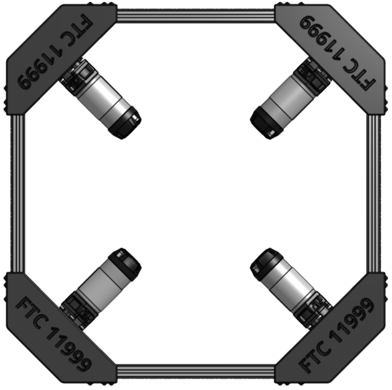
X Drive - This is the 4 Wheel holonomic drive. We call it X Drive because it makes an X shape.
Vector - Omni-Wheel holonomic drive systems highly rely on wheels abilities to side on two directions. The combination of these directions with other wheels added allows the robot to create a vector. Which is the magnitude and direction of combined wheels.
¶ What is X-Drive?
X-Drive, also called 4-wheel holonomic drive, is a drivetrain that lets a robot move in any direction—forward, backward, sideways, diagonally, and rotate.
It works in a way that’s similar to a mecanum drive, but the difference is in the type of wheels and the angle they’re mounted at. In an X-Drive, the wheels are omni-wheels set at a 45° angle, forming an “X” shape when viewed from above.
X-Drive was one of the first multi-directional drive systems in robotics. Out of all the drivetrain options, it’s one of the simplest to build and understand, while still being very capable.
Pros
- Easy to build
- Cheap
- Omni-Directional Drive
- Has good agility
Cons
- Easy to push around
- Less efficient movement
- Takes up lots of internal space
Here is an example of robots using Holonomic drive:
https://www.youtube.com/watch?v=WkwWFsZaGCE
¶ Programming X-Drive
Creating tne Motors - First we need to create our motors. 2 for the front and 2 for the back.
We will add this code to the public class Robot.
Java
DcMotorSimple frontLeftDrive = null;
DcMotorSimple frontRightDrive = null;
DcMotorSimple backLeftDrive = null;
DcMotorSimple backRightDrive = null;
Make sure the following import has been added near the other imports.
Java
import com.qualcomm.robotcore.hardware.DcMotorSimple;
Device Relation - We need to attach the device names to our variables.
Reminder that each motor and sensor must be setup through the driver station under configurations.
hardwareMap.get() - Retrieves the (first) device with the indicated name which is also an instance of the indicated class or interface. If no such device is found, an exception is thrown.
public <T> T get(java.lang.Class<? extends T> classOrInterface,
                 java.lang.String deviceName)
Example
DcMotor motorLeft = hardwareMap.get(DcMotor.class, "motorLeft");
ColorSensor colorSensor = hardwareMap.get(ColorSensor.class, "myColorSensor");
This code will need to be added to the class called runOpMode.
Java
frontLeftDrive = hardwareMap.get(DcMotorSimple.class, "frontLeftDrive");
frontRightDrive = hardwareMap.get(DcMotorSimple.class, "frontRightDrive");
backLeftDrive = hardwareMap.get(DcMotorSimple.class, "backLeftDrive");
backRightDrive = hardwareMap.get(DcMotorSimple.class, "backRightDrive");
Motor Directions
This may not be the case for every robot, but generally we want each side to drive opposite of each other. The setup with the Left side going in reverse, and the right side going forward is normal.
frontLeftDrive.setDirection(DcMotor.Direction.REVERSE);
backLeftDrive.setDirection(DcMotor.Direction.REVERSE);
frontRightDrive.setDirection(DcMotor.Direction.FORWARD);
backRightDrive.setDirection(DcMotor.Direction.FORWARD);
Once you have that added. It should look something like this
Java
package org.firstinspires.ftc.teamcode;

import com.qualcomm.robotcore.hardware.DcMotor;

...

public class Robot extends LinearOpMode {

    DcMotorSimple frontLeftDrive = null;
    DcMotorSimple frontRightDrive = null;
    DcMotorSimple backLeftDrive = null;
    DcMotorSimple backRightDrive = null;

    @Override
    public void runOpMode() {

        frontLeftDrive = hardwareMap.get(DcMotorSimple.class, "frontLeftDrive");
        frontRightDrive = hardwareMap.get(DcMotorSimple.class, "frontRightDrive");
        backLeftDrive = hardwareMap.get(DcMotorSimple.class, "backLeftDrive");
        backRightDrive = hardwareMap.get(DcMotorSimple.class, "backRightDrive");

        frontLeftDrive.setDirection(DcMotor.Direction.REVERSE);
                backLeftDrive.setDirection(DcMotor.Direction.REVERSE);
                frontRightDrive.setDirection(DcMotor.Direction.FORWARD);
                backRightDrive.setDirection(DcMotor.Direction.FORWARD);

        ...

    }
}
Gamepads (Joysticks)
From the driver station, we are allowed to use two gamepads. One for each driver. Typlically we use gamepad1 for the drive system.
Omni-Directional Gamepad Layout

We use the left joystick for forward/backward/left/right movement, and the right joystick for rotational movement.
For example, If we want to rotate the robot. We use the right joytick (right_stick) and we are using the y axis (_y).
- Axial - Foward/Backward Movement
- Lateral - Left/Right Movement
- Yaw - Rotational Movement
We want to inverse the axial direction (forwards/backwards), this is so the robot drives forwards instead of driving backwards.
Java
double axial   = -gamepad1.left_stick_y;  // Note: pushing stick forward gives negative value
double lateral =  gamepad1.left_stick_x;
double yaw     =  gamepad1.right_stick_x;
Robot Movement (Kinematics)
The robot movement for X-Drive is exactly the same as mecanum. The only diffrence between the two is the physical construction.
When we are driving, we are using the driving wheel volocity and the free wheel volocity to create a vector in the desired direction. There are two ways we can actually calculate the wheel speed matrix. We can use linear algebra, or trigonometry. Both have near similar outcome to robotic movment. In this case we will being using algebraic math as it's the easiest to understand.
Keep in mind when we are dealing with robot movement (kinematics). We are creating a movement model that does not take external forces or factors into account. For Example, when we apply 100% voltage to the motors, each motor will slightly move at a diffrent speed.
We are going to focus on the three main movements; Axial, Lateral, and Yaw. Which are the building blocks of holonomic drive systems. We are going to build our Axial movment by both sides driving diagonally.
45 Degree X+Y+ Movement
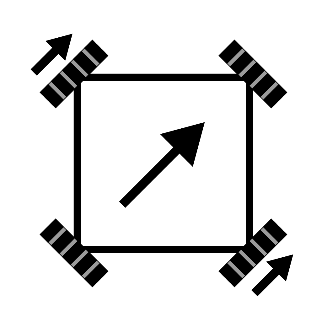
With both motors directly opposite from each other driving forward, we are given diagonal movment. Whether this is positive or negitive inputs from the controllers.
45 Degree X+Y- Movement

In order to achive each direction in the x and y axis (Forwards/Backwards/Left/Right) We need to rely on the wheel velocities to cancel out and create a vector in the direction we want to head. If we want to drive forward. We need to drive both the right and left side motors againced one another in the correct direction.
Axial Direction
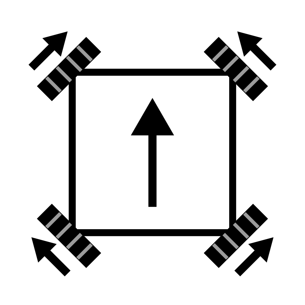
If we where to combine these two movements togther we would drive forward.
When we are building our movement model. We are only focusing on the forward direction. Relying on the changes in the game pads joystick axis to give us positive and negitive values. Joysticks output -1 thru 1, and the motors expect the input to be the same. 1 meaning give the motor full power.
Lets build our matix for our drive system:
frontLeftPower = axial + lateral
frontRightPower = axial - lateral
backLeftPower = axial - lateral
backRightPower = axial + lateral
For example if we want to drive forward at full power. We would input these values axial = -1 then we are giving the following inputs for the motors
frontLeftPower = -1 + 0
frontRightPower = -1 - 0
backLeftPower = -1 - 0
backRightPower = -1 + 0
Nothing to complicated. Except, if you notice, all these values are the same. How come the robot drives forward? That all comes down to our inital motor direction setup. This aligns the mecanum drive system and the x-drive system to use the same code. In reality, our motors are actaully going:
frontLeftPower = 1 + 0
frontRightPower = -1 - 0
backLeftPower = 1 - 0
backRightPower = -1 + 0
Which aligns to our forward movement diagram above.
This is what it looks like if we were to drive right at full power in the lateral movement:
frontLeftPower = 0 + 1
frontRightPower = 0 - 1
backLeftPower = 0 - 1
backRightPower = 0 + 1
The reason why we are adjusting the directions in the lateral movement (left/right) with + and - is because we need the motors front and back motors to drive opposite of each other. In combination of the motor configurations. The corrections givien are non-intuitive.
Rotation, is the last simlpe movement we need to cover. Similar to how diaginal movements are achieved, these are more native to how the motors rotate.
Rotation (Yaw) Movement
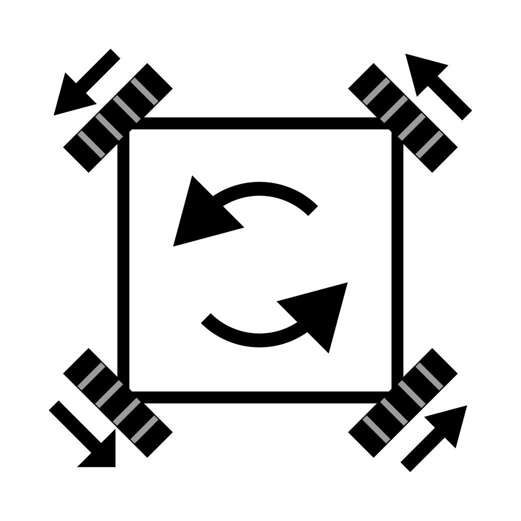
If we were to drive all the motors in the same direction we will rotate.
Now that we have an understanding on how the motor power equations work. Lets go ahead and combine all the movements together.
Java
// Combine the joystick requests for each axis-motion to determine each wheel's power.
// Set up a variable for each drive wheel to save the power level for telemetry.
double frontLeftPower  = axial + lateral + yaw;
double frontRightPower = axial - lateral - yaw;
double backLeftPower   = axial - lateral + yaw;
double backRightPower  = axial + lateral - yaw;
Last thing we need to do is now is tell our motors to move using our equations. Simply, we will use the setPower() method.
Java
// Send calculated power to wheels
frontLeftDrive.setPower(frontLeftPower);
frontRightDrive.setPower(frontRightPower);
backLeftDrive.setPower(backLeftPower);
backRightDrive.setPower(backRightPower);
Lets put that all together. Before you start driving though. Continue on to the next section to normalize the power.
// Combine the joystick requests for each axis-motion to determine each wheel's power.
// Set up a variable for each drive wheel to save the power level for telemetry.
double frontLeftPower  = axial + lateral + yaw;
double frontRightPower = axial - lateral - yaw;
double backLeftPower   = axial - lateral + yaw;
double backRightPower  = axial + lateral - yaw;

...

// Send calculated power to wheels
frontLeftDrive.setPower(frontLeftPower);
frontRightDrive.setPower(frontRightPower);
backLeftDrive.setPower(backLeftPower);
backRightDrive.setPower(backRightPower);
If you want a more in depth explination, or want to go into the trigonometry side of 4-wheel holonomic drive. Please watch this video:
https://www.youtube.com/watch?v=NcOT9hOsceE
Normalize Power
When giving our motors power, the robot movement equations can result in greater than 100% power. This can give 300% to each motor, how ever amazing this can look. This would be nearly impossible to control the robot, because it will go from 0% to 100% with little to no control in between.
First we need to find the current max input given to each motor. The method we are using is Math.max(). What this does is compare two values and finds which one is higher. For example:
Math.max(10, 20) // This will result that 20 is higher than 10
Now that we know that. We are going to test each motor power and find the highest one. Also we are going to use a double (0.00 decimal) variable called max.
double max;

...

max = Math.max(Math.abs(frontLeftPower), Math.abs(frontRightPower));
max = Math.max(max, Math.abs(backLeftPower));
max = Math.max(max, Math.abs(backRightPower));
Now that we found the highest, we need to test if the max is greater than 100% (1.0), and if it is then divide the motor power by the max power. The way we are doing it below is the same as frontLeftPower = frontLeftPower/max.
if (max > 1.0) {
    frontLeftPower  /= max;
    frontRightPower /= max;
    backLeftPower   /= max;
    backRightPower  /= max;
}
Once we have that, lets add this to our code to make driving easier and less crazy.
Java
double max;

...

// Normalize the values so no wheel power exceeds 100%
// This ensures that the robot maintains the desired motion.
max = Math.max(Math.abs(frontLeftPower), Math.abs(frontRightPower));
max = Math.max(max, Math.abs(backLeftPower));
max = Math.max(max, Math.abs(backRightPower));

if (max > 1.0) {
    frontLeftPower  /= max;
    frontRightPower /= max;
    backLeftPower   /= max;
    backRightPower  /= max;
}

...
Finished X-Drive Code
Congrats! We now have our x-drive code ready. This should allow the robot to drive relative to its own perspective.
            //X Drive Math

            double max;

            double axial   = -gamepad1.left_stick_y;  // Note: pushing stick forward gives negative value
            double lateral =  gamepad1.left_stick_x;
            double yaw     =  gamepad1.right_stick_x;

            // Combine the joystick requests for each axis-motion to determine each wheel's power.
            // Set up a variable for each drive wheel to save the power level for telemetry.
            double frontLeftPower  = axial + lateral + yaw;
            double frontRightPower = axial - lateral - yaw;
            double backLeftPower   = axial - lateral + yaw;
            double backRightPower  = axial + lateral - yaw;

            // Normalize the values so no wheel power exceeds 100%
            // This ensures that the robot maintains the desired motion.
            max = Math.max(Math.abs(frontLeftPower), Math.abs(frontRightPower));
            max = Math.max(max, Math.abs(backLeftPower));
            max = Math.max(max, Math.abs(backRightPower));

            if (max > 1.0) {
                frontLeftPower  /= max;
                frontRightPower /= max;
                backLeftPower   /= max;
                backRightPower  /= max;
            }

            // Send calculated power to wheels
            frontLeftDrive.setPower(frontLeftPower);
            frontRightDrive.setPower(frontRightPower);
            backLeftDrive.setPower(backLeftPower);
            backRightDrive.setPower(backRightPower);
Want to download the robot relative code? Click Here
¶ Adding Field Orientation (Field Relative Drive)
IMU Setup
Adding the IMU is very similar to how we added our motors. There are a couple of options for using a IMU. Either use the built in IMU on the robot controller, or add an external one like the Rev 9 Axis IMU.
IMU Class
We will add this code to the public class Robot.
Java
IMU imu;
Make sure the following import has been added near the other imports.
Java
import com.qualcomm.robotcore.hardware.IMU;
Device Relation - We need to attach the device names to our variables.
Reminder that each motor and sensor must be setup through the driver station under configurations.
hardwareMap.get() - Retrieves the (first) device with the indicated name which is also an instance of the indicated class or interface. If no such device is found, an exception is thrown.
public <T> T get(java.lang.Class<? extends T> classOrInterface,
                 java.lang.String deviceName)
Example
DcMotor motorLeft = hardwareMap.get(DcMotor.class, "motorLeft");
ColorSensor colorSensor = hardwareMap.get(ColorSensor.class, "myColorSensor");
This code will need to be added to the class called runOpMode.
Java
imu = hardwareMap.get(IMU.class, "driveGyro");
Yaw Reset
At times, the gyro in the IMU can have drift during a match. However it doesn't happen by much. Its best to give the driver the ability to reset the gyro.
We take the gamepad1 and use the start button to reset. This button is best because its out of the way and isn't an east thing to press. Using the resetYaw() method, we will have successfully reset the rotation.
if(gamepad1.start) {
    imu.resetYaw();
}
Should look like this once you have that added.
package org.firstinspires.ftc.teamcode;

...

import com.qualcomm.robotcore.hardware.IMU;

...

public class Robot extends LinearOpMode {

        ...

    IMU imu;

    @Override
    public void runOpMode() {

        ...

        imu = hardwareMap.get(IMU.class, "driveGyro");

        ...

        while (opModeIsActive()) {

        		...

        		if(gamepad1.start) {
                imu.resetYaw();
          	}

            ...
        }
    }
}
Field Relative Math
The concept of the field relative math is relativly simple. Although it takes an understanding of trigonometry. We will attempt to simplify it.
First we need to know the diffrence cartesian coordinates and polar coordinates. Cartesian is the system the robot is driving in, imagine sheet of graph paper where we have x and y axis. For example when we are driving forward our robot is experiancing forward in the x axis. When we strafe right, the robot is moving in the y axis. Because our gamepads use x and y axis, this makes sense to directly control the robot with x and y in mind.
When we are using field relative, our robot needs to convert our cartesian system into a polor system for a brief moment. Polor coordnates is similar to how a you see a radiar screen.
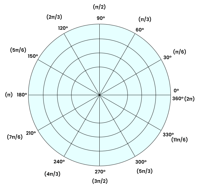
We use radians because it better defines a circle than degreese does. If you look at the graph you will see 2π that is radians you will see that next to 0°.
To convert from cartesian coordinates to polar coordinates, we use the following:
                        // First, convert direction being asked to drive to polar coordinates
            double theta = Math.atan2(forward, right);
            double r = Math.hypot(right, forward);
Thata means angle and r means radian. We use the built in math methods Math.atan2() and Math.hypot() to find both.
To recalculate our angle (thata Θ), we need to grab our robot's current angle subtract the IMU gyro yaw angle. This is the point where we go from robot relative to field relative.
// Second, rotate angle by the angle the robot is pointing
            theta = AngleUnit.normalizeRadians(theta -
                    imu.getRobotYawPitchRollAngles().getYaw(AngleUnit.RADIANS));
Finally we convert back to cartesian by using the r we saved before use sine and cosine with thata.
                        // Third, convert back to cartesian
            double newForward = r * Math.sin(theta);
            double newRight = r * Math.cos(theta);
This is what we should have left.
                        //Field Relative Math

            // First, convert direction being asked to drive to polar coordinates
            double theta = Math.atan2(forward, right);
            double r = Math.hypot(right, forward);

            // Second, rotate angle by the angle the robot is pointing
            theta = AngleUnit.normalizeRadians(theta -
                    imu.getRobotYawPitchRollAngles().getYaw(AngleUnit.RADIANS));

            // Third, convert back to cartesian
            double newForward = r * Math.sin(theta);
            double newRight = r * Math.cos(theta);
Alternative Method
You might be wondering why we go through the trouble of converting Cartesian → polar → Cartesian. The reason is that it’s easier to understand conceptually — you just subtract the robot’s yaw angle from the gamepad input angle (theta).
That said, you can stay entirely in Cartesian by using the rotation matrix shown below. It avoids the back-and-forth conversion and looks a bit cleaner in code.
double yaw = imu.getRobotYawPitchRollAngles().getYaw(AngleUnit.RADIANS);

// Rotation matrix math
double newRight   = right * Math.cos(-yaw) - forward * Math.sin(-yaw);
double newForward = right * Math.sin(-yaw) + forward * Math.cos(-yaw);
Implementation
Now we need to impliment this with our exsisting X-Drive code. In order to do so, we need ro rename our gamepad axis to forward and right.
                        //Driver Game Pad - Change the name to forward and right
            double forward = gamepad1.left_stick_y;
            double right = gamepad1.left_stick_x;
Then name post the values to axial and lateral.
                        double axial = -newForward; // Note: pushing stick forward gives negative value
            double lateral = newRight;
There we are, should look like this! Now the robot will drive in Field Relative.
package org.firstinspires.ftc.teamcode;

...

import com.qualcomm.robotcore.hardware.IMU;

...

public class Robot extends LinearOpMode {

        ...

    IMU imu;

    @Override
    public void runOpMode() {

        ...

        imu = hardwareMap.get(IMU.class, "driveGyro");

        ...

        while (opModeIsActive()) {

        		//Driver Game Pad - Change the name to forward and right
            double forward = gamepad1.left_stick_y;
            double right = gamepad1.left_stick_x;

        		if(gamepad1.start) {
                imu.resetYaw();
          	}

            //Field Relative Math

            // First, convert direction being asked to drive to polar coordinates
            double theta = Math.atan2(forward, right);
            double r = Math.hypot(right, forward);

            // Second, rotate angle by the angle the robot is pointing
            theta = AngleUnit.normalizeRadians(theta -
                    imu.getRobotYawPitchRollAngles().getYaw(AngleUnit.RADIANS));

            // Third, convert back to cartesian
            double newForward = r * Math.sin(theta);
            double newRight = r * Math.cos(theta);

            //X-Drive Math

            ...

            double axial = -newForward; // Note: pushing stick forward gives negative value
            double lateral = newRight;

            ...
        }
    }
}
Want to download the field relative code? Click Here
¶ Documents and Links
Code:
X-Drive Code - Robot Relative
X-Drive Code - Field Relative
Related Guides: